F9 Capra Portal
Aluminum Axle Housing


M2 Hex Driver
M2.5 Drill Bit
M3 Tap

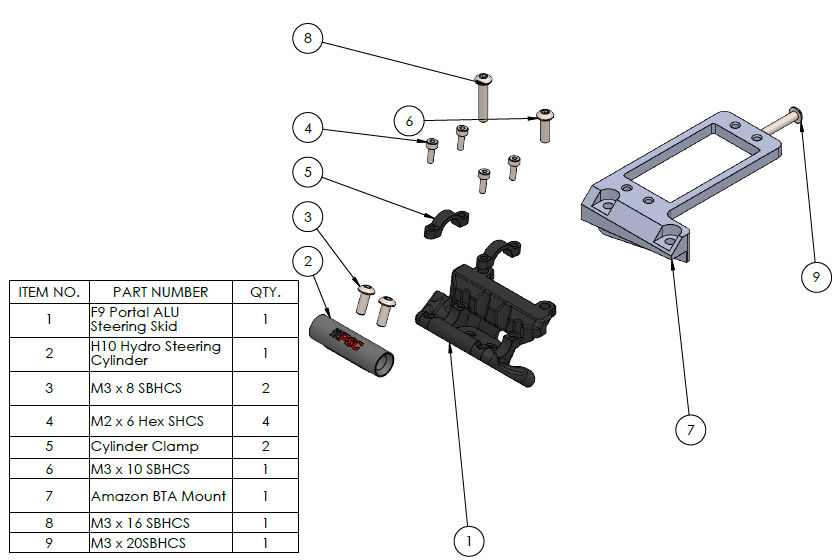
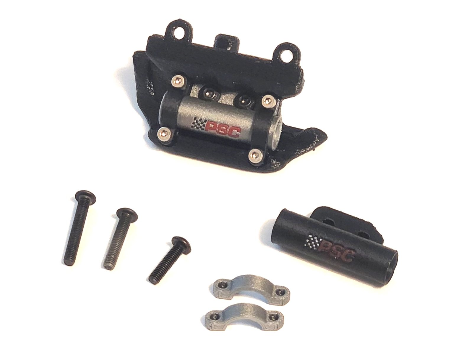
Skid
Silver and Black Cylinder
Silver and Black Clamps (Clamps are compatible with the H10 stock clamps or equivalent)
All Mounting hardware
M4x30mm stud – Qty. 2
M3x25mm screw (retained from the passenger side of the axle)
M3x30mm
*Incision H10 Hydro Ram Steering Set - SKU: IRC00192
*2 add’l Vanquish rod ends - SKU: IRC00010 (or equivalent)
*Only required if you purchased the Partial Assembly kit version
Partial Assembly Kit
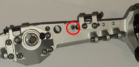
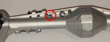
1- Take a M2.5 drill bit and drill through from the back of the axle through the existing threaded hole, the hole is tapered so it should self center. Drill through the last bit of the taped hole for the BTA mount.
2- Use the M3 Tap to chase the original threads from the back of the axle. Then proceed to tap all the way through the axle housing
4- Place M3x16mm Button head screw in the right BTA mount hole and the M3x10mm in the left, use M2 hex driver to tighten the bolts.
3- Place Skid onto front of axle. place BTA mount on the back of the axle. Place M3x20mm Button head screw in the hole through the differential housing, hold the skid tight in place as you tighten the bolt with a M2 hex driver.


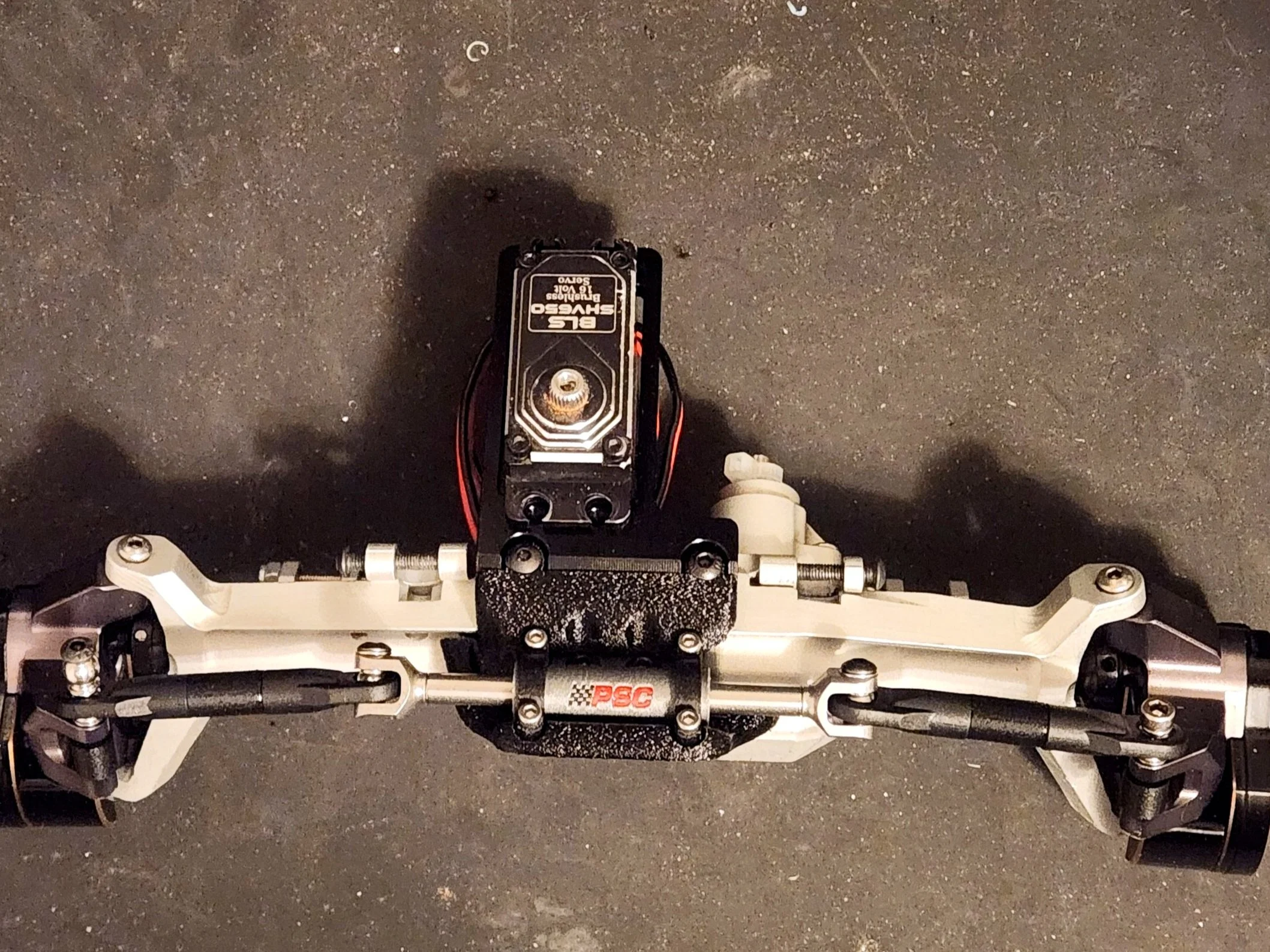
Full Assembly with Steering Ram kit:
5- To assemble the short steering links, take 4 standard Incision end links, insert the supplied pillow balls from the Steering Kit. I took a M4x30mm stud, Slide the ram through the printed cylinder, bolt on yokes supplied in the Incision kit and install the short linkages. This setup is a high steer, and is mounted on the top of the knuckle. Place the links to the topmost surface of the Knuckle, place a spacer where the old linkage would have gone. I would use a M3X30mm for the servo linkage side and a make sure the bolts that hold the linkage through the ram are facing up to clear the skid plate. The H10 links in the Incision kit do not work, they are too short.