F10 Straight

Plastic Axle Housing

An exploded view diagram of a motorcycle steering system assembly, showing various numbered parts such as a steering skid, hydraulic steering cylinder, mounting brackets, screws, and adapters with a parts list in the bottom right corner.
Tools needed for a project listed with icons and text including M1.5 Hex Driver, M2 Hex Driver, 90° Chamfer bit, 1/8” drill bit, and drill driver.
Text document listing supplies, including a ski, grey and black cylinder, grey and black clamps, right mount adapter, and mounting hardware.

Partial Assembly

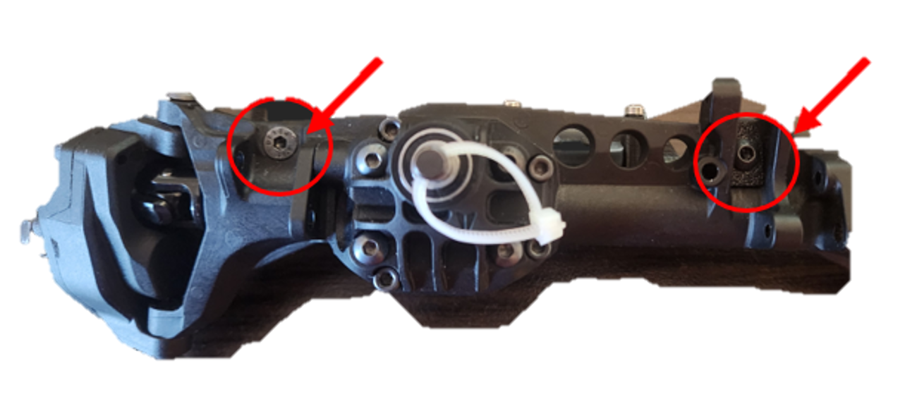
1-     Drill the 1/8” bit through the blind pocket on the truss front. The hole is slightly tapered and will self-center.

A black robotic or mechanical device with various geometric shapes and components, including a prominent middle section, mounted on a light-colored surface with a plain white background. A red arrow points to a small circular feature on the device.

2-     Use the chamfer bit to taper the backside of the newly drilled hole. Only go deep enough to bury the flat screw head

Close-up of a black electric car steering lock with a red arrow pointing to a specific part.
Close-up of a mechanical component, likely part of a machine or device, with an arrow pointing to a specific area, circled in red.

3-   Place Skid onto front of axle. Place Button head screw with RIGHT MOUNT ADAPTER correctly oriented so it matches the contours of the back side of the truss and axle, use M2 hex driver to tighten the bolt by hand. It will snug up. Do not over tighten! Place the flat head screw on the left and tighten by hand until snug.

Close-up of a mechanical device, with a red circle and arrow pointing to a specific part near the top right, indicating a bolt or screw being loosened or tightened, part of a machine component or engine.
Close-up of a mechanical or electronic component, possibly a part of a firearm or machinery, with two screws circled in red.
Close-up of a black automotive or machinery component with a red arrow pointing to a specific screw or bolt.

Full Assembly with Steering Ram kit:

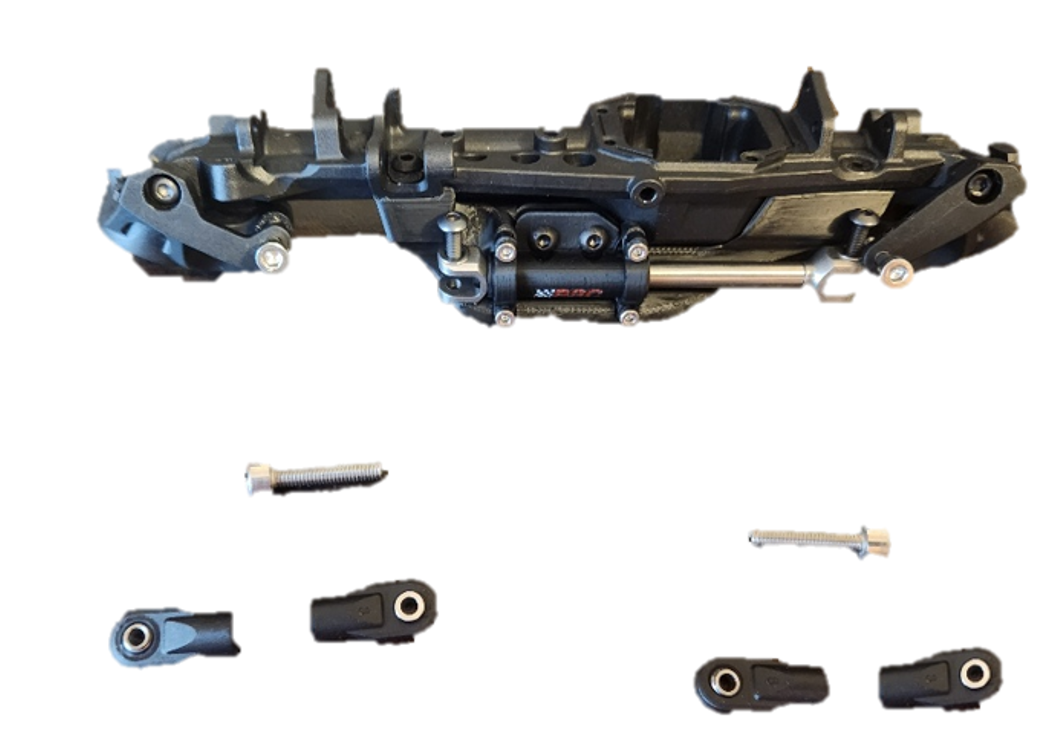
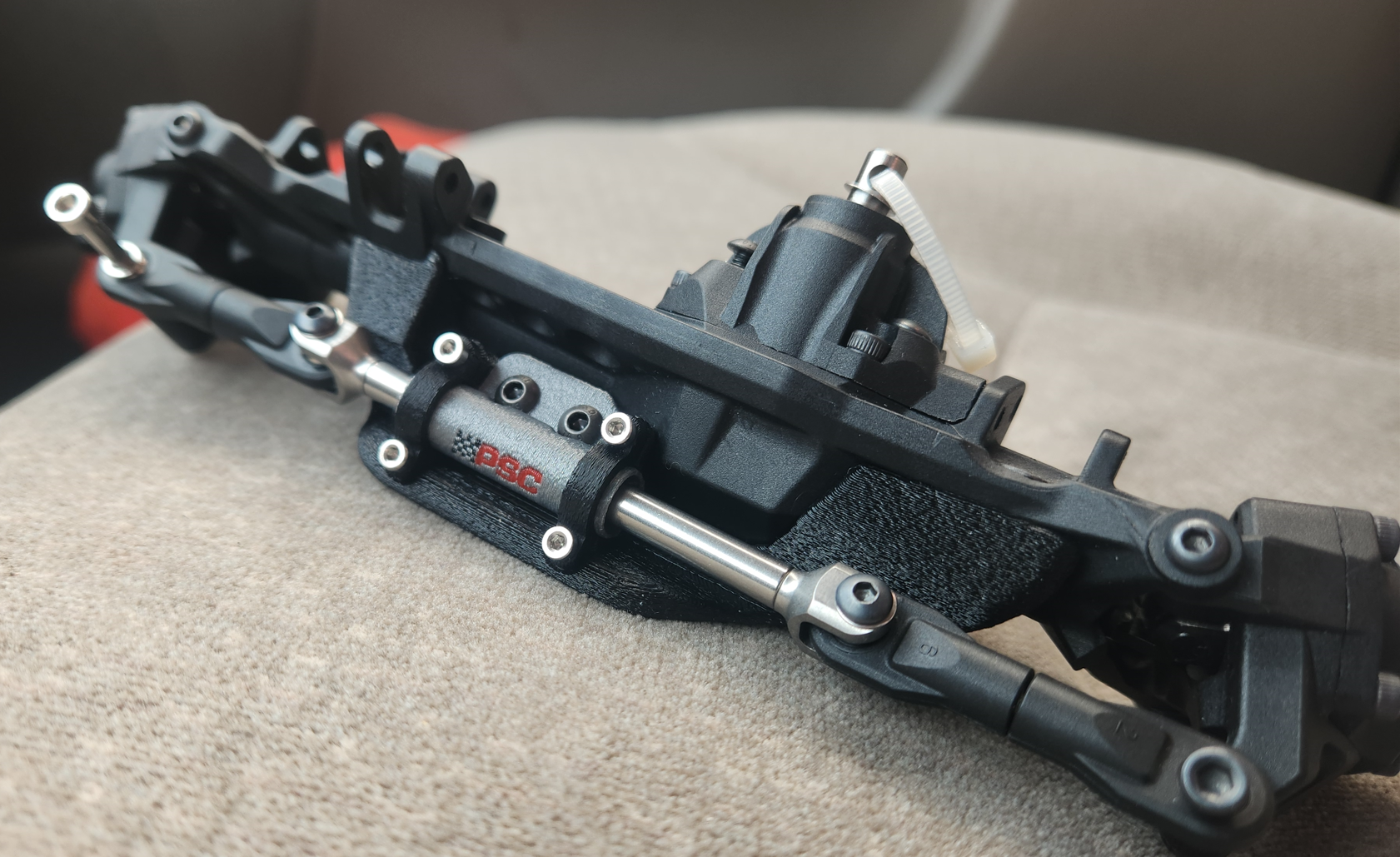
4-     To assemble the short steering links, take 4 standard Incision end links, insert the supplied pillow balls from the Steering Kit. I took a M4x20mm stud, if you don’t have one you can use a M4x20mm SHCS and used a cutoff wheel to remove the head and use the remaining 18mm-19mm stud length to join the end links together. Slide the ram through the printed cylinder, bolt on yokes supplied in the Incision kit and install the short linkages. This setup is a high steer, and is mounted on the top of the knuckle. Place the links to the topmost surface of the Knuckle, place a spacer where the old linkage would have gone. I would use a M3X30mm for the servo linkage side and a make sure the bolts that hold the linkage through the ram are facing up to clear the skid plate. The H10 links in the Incision kit do not work, they are too long.

Disassembled black motorcycle foot pedal with attached parts and screws on a white background.
Two black metal bicycle brake lever pivot components with screws on a white background.
Close-up of a bicycle rear derailleur with exposed components, including the derailleur cage, and a black mounting bracket, resting on a beige surface.